AGROBOT

Where My Engineering Journey Began.

My Role

Lead Mechanical Designer

Project Timeline

2023-2024

Tools & Core Skills Acquired

SOLIDWORKS, 3D CAD Modeling, 3D Printing, Mechanical Assembly, Arduino

Engineering and agricultural technology

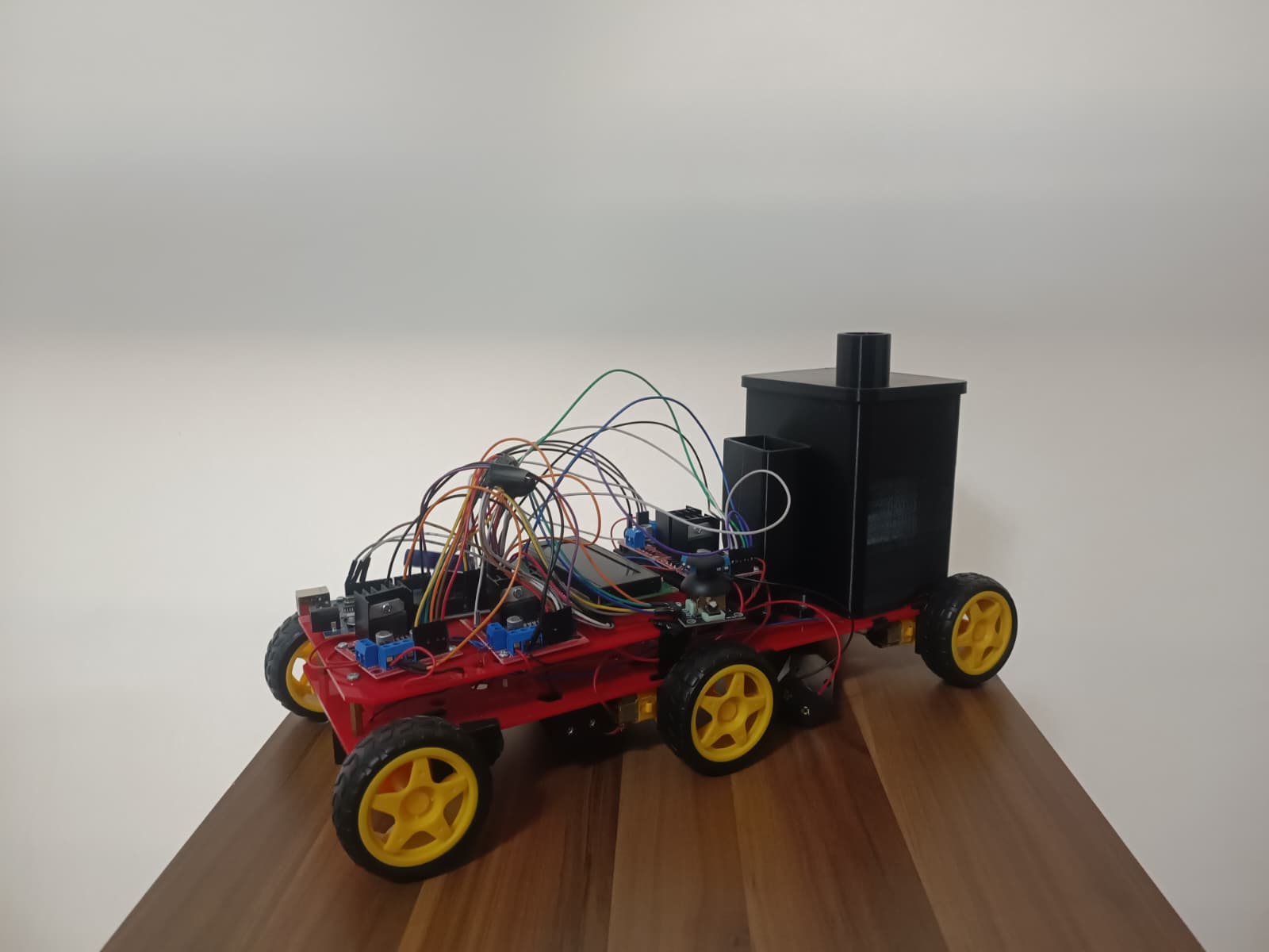
AGROBOT Prototype

The Problem We Solved

The global demand for food is rising, yet traditional agricultural machinery remains prohibitively expensive for many farmers. We identified an opportunity to create an accessible, low-cost solution that could automate the most labor-intensive tasks: soil excavation, seeding, and watering.

Our answer was a prototype, AGROBOT. Our primary goal was to reduce human labor and operational expenses by engineering a small-scale autonomous rover capable of seeding and irrigation. To achieve this, we built a compact, battery-powered 6-wheel rover controlled by an Arduino MEGA. It was designed to autonomously navigate a predefined area while synchronously digging, dropping seeds from a custom motorized hopper, watering them via a gravity-fed solenoid system, and closing the soil back up—all in a single continuous pass. By designing almost all the core components ourselves and manufacturing them via 3D printing, we aimed to prove that modern agricultural automation didn't have to be expensive.
Designing for the Dirt

My primary responsibility was bringing the robot's physical form to life. I handled the 3D CAD modeling and overall mechanical design, ensuring that every printed part interacted perfectly with the commercial chassis and electronic components. I broke the mechanical system down into functional modules:

The Digger

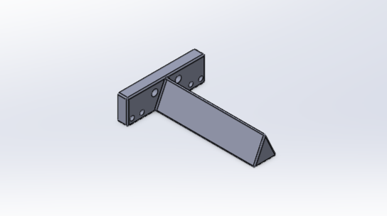
I designed the Digger to dig the soil up to 40mm deep. To minimize the impact forces generated by the terrain, I used curved geometries rather than sharp corners. The triangular shape naturally parted the earth as the robot moved forward, completely eliminating the need for a dedicated motor for excavation.

The Digger CAD

The Digger CAD Model

The Seeding Unit

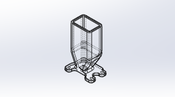
I modeled a rectangular, funnel-shaped hopper that utilized gravity to feed seeds. At the base, I designed a specialized, weight-reduced cylindrical disk attached to a DC motor. As the disk rotated, custom cavities caught individual seeds and dropped them into the soil at precise intervals.

Seeding Unit CAD

Seeding Unit CAD Model

The Closer

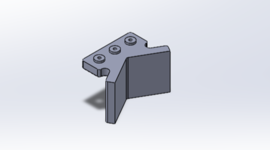
After the seeds were dropped, the soil needed to be covered. I engineered a passive mechanical component featuring two wings angled at 120 degrees. As the robot drove forward, these wings reliably guided the excavated soil back into the trench over the seeds.

The Closer CAD

The Closer CAD Model

The Watering System

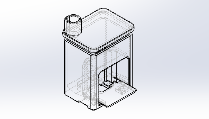
I designed a custom platform and a 400ml water tank to house a 1/4 inch solenoid valve. I specifically designed the tank with a high vertical profile to maintain adequate fluid pressure as the water level decreased during operation.

Watering System CAD

Watering System CAD Model

Wiring an Arduino

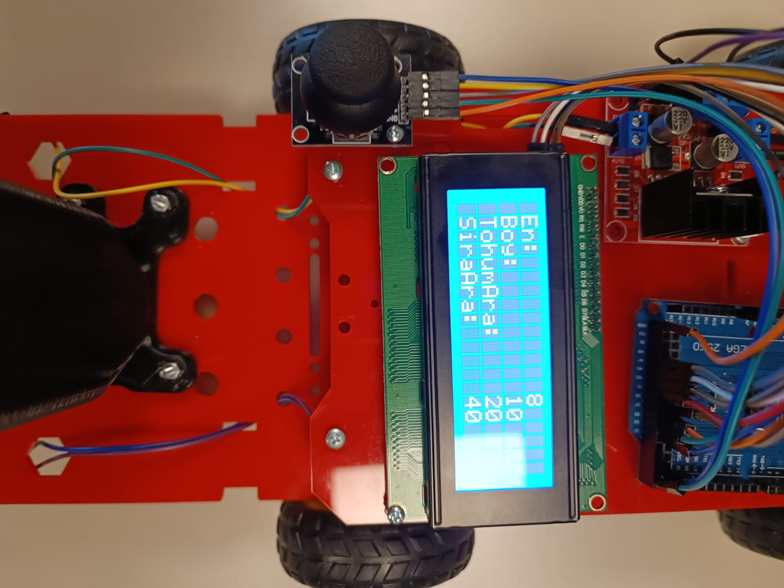
Input Screen

Microcontroller close up

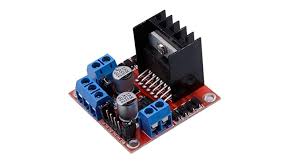
L298N Driver

Bringing It to Life

Beyond the mechanical CAD work, I physically assembled the robot and played a key role in assisting with the electronics. This was my crash course in making digital logic control physical motors.

We utilized an Arduino MEGA 2560 as the main processor, wiring it to L298N motor drivers to control the 6V 250 RPM DC motors driving the wheels and the seeding disk.

To make the robot autonomous yet configurable, we integrated a 4x20 I2C LCD screen alongside a 2-axis joystick. This setup allowed the user to input the specific dimensions of the field and configure the seed spacing before the robot executed its path-finding algorithm.

First Steps in My Engineering Path

Every engineer has that one foundational project that pulls them from theory into reality. For me, it was AGROBOT. This wasn't just a technical challenge; it was the project where I taught myself how to build things from scratch.

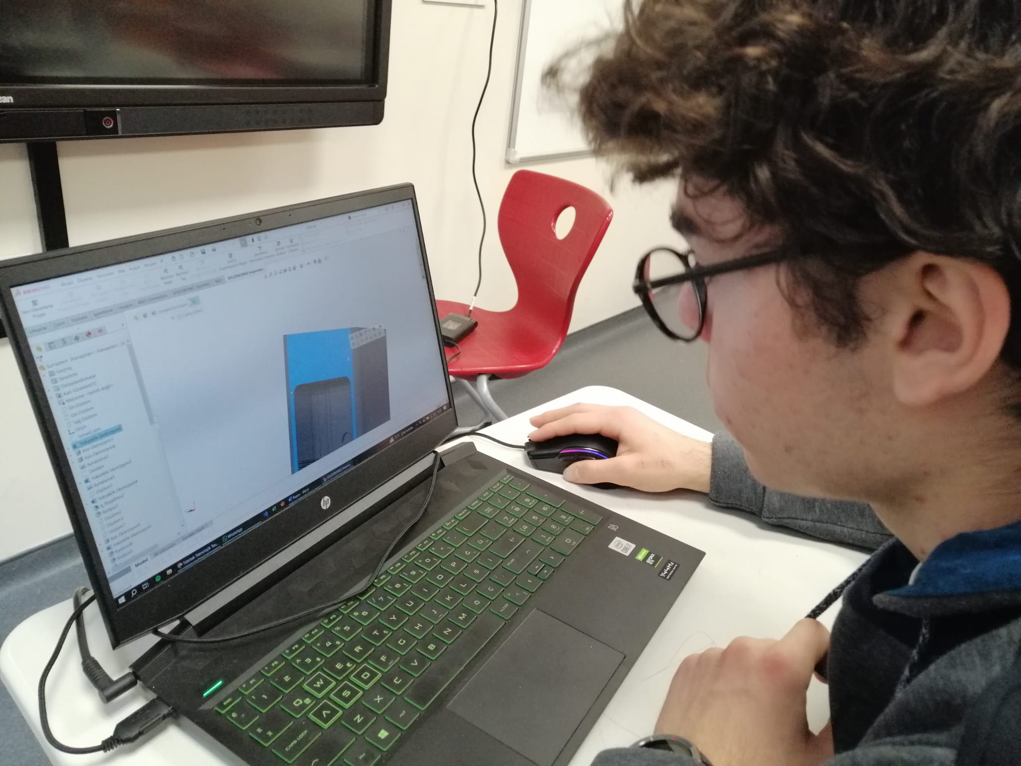
Before AGROBOT, my knowledge of 3D design and electronics was entirely conceptual. Through this initiative, I plunged headfirst into SOLIDWORKS to model moving parts, navigated the logic of Arduino microcontrollers, and learned the intricate dance of mechatronics. It taught me the most crucial lesson in engineering: a design is only as good as its physical assembly.

Student learning 3D design

Early CAD Learning & Development

Key Takeaways

The foundational skills I built during the AGROBOT project.

Parametric CAD Modeling

Transitioning from sketches to 3D spatial environments in SOLIDWORKS, learning how to design components specifically optimized for 3D printing.

Mechatronics Integration

Understanding the physical space required for wires, sensors, and microcontrollers, and how to design part structures that accommodate them.

Microcontroller Logic

Gaining hands-on experience with Arduino architecture, using analog and digital pins to control solenoids and DC motors.

Problem Solving in Reality

Realizing that the perfect digital CAD model will inevitably face friction, tolerances, and hardware limitations in the real world.

Hardware Troubleshooting

Learning to systematically debug physical systems—from checking jumper wire continuity to diagnosing voltage drops across motor drivers.

Design for Manufacturing (DFM)

Balancing mechanical strength with weight reduction, especially in the custom seeding disk and the gravity-fed water tank design.

AGROBOT was the spark. It proved to me that with CAD, electronics, and a 3D printer, I could build systems that can make a difference.